Danger
This is a preview of the elektrophon website, the content may not be accurate and is subject to change without any notice.
The AD/AR contains two envelope circuits and one pulse timer. Both will have a trigger at the end of the envelope or delayed pulse. The end of envelope is not connected to another input, those must be patched. The output of the delayed pulse is connected to the input of the first envelope.
Figure 1: Kontur Block Diagram
Figure 2: Kontur schematic
Figure 3: AD/AR analysis
In this circuit U1 is a latch. It goes high when there is an input signal.
Figure 4: End of Envelope analysis
For the end of envelope trigger we use another comperator. This comperator will trigger at about 0.6V. The trigger starts on he falling edge and ends on the rising edge at 0.6 V again (Orange). An AND gate will limit the trigger to the falling gate. One input is the output of the comperator the other the inverted output of the latch.
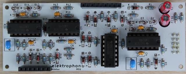
Figure 5: Kontur Board
| # | reference | value | description | |
| 2 | C1 C2 | 22u | Aluminium Electrolytic Capacitors (50V, D=6.3 mm, LS=2.5 mm) | |
| 7 | C3 C4 C5 C6 C8 C10 C11 | 0.1u | Multilayer Ceramic Capacitors MLCC (50V, L=4 mm, W=2.5 mm, LS=2.5 mm) | |
| 2 | C7 C9 | 4.7u | Multilayer Ceramic Capacitors MLCC (25V, L=6 mm, W=5.5 mm, LS=5 mm) | |
| 14 | D1 D4 D7 D8 D9 D10 D11 D12 D15 D18 D19 D20 D21 D22 | 1N4148 | Small Signal Diode (DO-35) | |
| 8 | D2 D3 D5 D6 D13 D14 D16 D17 | 1N4148 | Small Signal Diode (DO-35) | |
| 1 | J1 | 01x09 Female | Board to Board Connectors (2.54 mm) | |
| 1 | J2 | 10 Pos | Pin Header IDC (2.54mm) | |
| 1 | J3 | 01x07 Female | Board to Board Connectors (2.54 mm) | |
| 4 | R1 R16 R19 R32 | 100k | Metal Film Resistors - Through Hole (L=3.6 mm, D=1.6 mm, 1%) | |
| 2 | R2 R20 | 27k | Metal Film Resistors - Through Hole (L=3.6 mm, D=1.6 mm, 1%) | |
| 2 | R3 R21 | 390k | Metal Film Resistors - Through Hole (L=3.6 mm, D=1.6 mm, 1%) | |
| 4 | R4 R9 R22 R25 | 47k | Metal Film Resistors - Through Hole (L=3.6 mm, D=1.6 mm, 1%) | |
| 2 | R5 R6 | 10 | Metal Film Resistors - Through Hole (L=3.6 mm, D=1.6 mm, 1%) | |
| 2 | R7 R23 | 470k | Metal Film Resistors - Through Hole (L=3.6 mm, D=1.6 mm, 1%) | |
| 2 | R8 R24 | 2.2k | Metal Film Resistors - Through Hole (L=3.6 mm, D=1.6 mm, 1%) | |
| 2 | R10 R26 | 10k | Metal Film Resistors - Through Hole (L=3.6 mm, D=1.6 mm, 1%) | |
| 2 | R11 R27 | 36k | Metal Film Resistors - Through Hole (L=3.6 mm, D=1.6 mm, 1%) | |
| 6 | R12 R14 R15 R17 R18 R28 | 1k | Metal Film Resistors - Through Hole (L=3.6 mm, D=1.6 mm, 1%) | |
| 2 | R13 R29 | 220 | Metal Film Resistors - Through Hole (L=3.6 mm, D=1.6 mm, 1%) | |
| 3 | U1 U2 U4 | LM324 | Low-Power, Quad-Operational Amplifiers | |
| 1 | U3 | 4001 | CMOS Quad 2-Input NOR Gate |
| # | reference | value | description | |
| 6 | D1 D2 D5 D6 D9 D10 | 1N4148W | Diode_SMD:D_SOD-123 | |
| 2 | D3 D4 | LED (Yellow) | LED 3mm low current | |
| 4 | D7 D8 D11 D12 | LED (Red) | LED 3mm low current | |
| 1 | J1 | 01x09 Male | Board to Board Connectors (2.54 mm) | |
| 1 | J2 | 01x07 Male | Board to Board Connectors (2.54 mm) | |
| 6 | J3 J4 J5 J6 J7 J8 | AudioJack2_SwitchT | 3.5mm Eurorack Jacks | |
| 6 | Q1 Q2 Q3 Q4 Q5 Q6 | MMBT3904 | NPN switching transistor (SOT23) | |
| 8 | R1 R2 R3 R4 R5 R6 R7 R8 | 2.2k | Metal Film Resistors - Through Hole (L=3.6 mm, D=1.6 mm, 1%) | |
| 6 | R9 R10 R13 R14 R17 R18 | 100k | Thick Film Resistors - SMD (0805) | |
| 6 | R11 R12 R15 R16 R19 R20 | 5.1k | Thick Film Resistors - SMD (0805) | |
| 2 | RV1 RV3 | 100k | Alpha 9 mm Pots – Vertical | |
| 2 | RV2 RV4 | 500k | Alpha 9 mm Pots – Vertical |
For mounting the LED's the long lead has to go to the round pad.
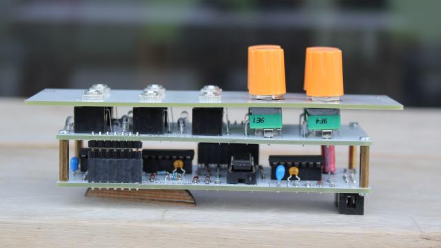
Figure 6: Kontur Side view
There is no calibration needed. But the potentiomenter knobs have to be aliged to center position.
There are two independent envelope generators which are not connected together.
simple usage
Connect a trigger signal to one of the inputs. The Envelope is on the OUT jack Adjust attack and Release time with the potentiometers
use the end of envelope signal
path the EOE to the second when the first envelope generator finishes it will trigger the second one
use as LFO
Connect the EOE to the input The module will not start with an envelope on its own, there must be an initial external trigger adjust the speed and waveform with the potentiometers