Danger
This is a preview of the elektrophon website, the content may not be accurate and is subject to change without any notice.
for the final circuit input and output buffering and biasing is needed. the buffering is done with opamps.
Figure 1: Block Diagram
first we design the input stage. the input voltage for the X signal should be 10mV and 20mV for the control voltage.
VoltageSource V5
VoltageSource V5
VoltageSource V5
| # | reference | value | description | |
| 2 | C1 C2 | 22u | Aluminium Electrolytic Capacitors (50V, D=6.3 mm, LS=2.5 mm) | |
| 7 | C3 C4 C5 C6 C8 C10 C11 | 0.1u | Multilayer Ceramic Capacitors MLCC (50V, L=4 mm, W=2.5 mm, LS=2.5 mm) | |
| 2 | C7 C9 | 4.7u | Multilayer Ceramic Capacitors MLCC (25V, L=6 mm, W=5.5 mm, LS=5 mm) | |
| 14 | D1 D4 D7 D8 D9 D10 D11 D12 D15 D18 D19 D20 D21 D22 | 1N4148 | Small Signal Diode (DO-35) | |
| 8 | D2 D3 D5 D6 D13 D14 D16 D17 | 1N4148 | Small Signal Diode (DO-35) | |
| 1 | J1 | 01x09 Female | Board to Board Connectors (2.54 mm) | |
| 1 | J2 | 10 Pos | Pin Header IDC (2.54mm) | |
| 1 | J3 | 01x07 Female | Board to Board Connectors (2.54 mm) | |
| 4 | R1 R16 R19 R32 | 100k | Metal Film Resistors - Through Hole (L=3.6 mm, D=1.6 mm, 1%) | |
| 2 | R2 R20 | 27k | Metal Film Resistors - Through Hole (L=3.6 mm, D=1.6 mm, 1%) | |
| 2 | R3 R21 | 390k | Metal Film Resistors - Through Hole (L=3.6 mm, D=1.6 mm, 1%) | |
| 4 | R4 R9 R22 R25 | 47k | Metal Film Resistors - Through Hole (L=3.6 mm, D=1.6 mm, 1%) | |
| 2 | R5 R6 | 10 | Metal Film Resistors - Through Hole (L=3.6 mm, D=1.6 mm, 1%) | |
| 2 | R7 R23 | 470k | Metal Film Resistors - Through Hole (L=3.6 mm, D=1.6 mm, 1%) | |
| 2 | R8 R24 | 2.2k | Metal Film Resistors - Through Hole (L=3.6 mm, D=1.6 mm, 1%) | |
| 2 | R10 R26 | 10k | Metal Film Resistors - Through Hole (L=3.6 mm, D=1.6 mm, 1%) | |
| 2 | R11 R27 | 36k | Metal Film Resistors - Through Hole (L=3.6 mm, D=1.6 mm, 1%) | |
| 6 | R12 R14 R15 R17 R18 R28 | 1k | Metal Film Resistors - Through Hole (L=3.6 mm, D=1.6 mm, 1%) | |
| 2 | R13 R29 | 220 | Metal Film Resistors - Through Hole (L=3.6 mm, D=1.6 mm, 1%) | |
| 3 | U1 U2 U4 | LM324 | Low-Power, Quad-Operational Amplifiers | |
| 1 | U3 | 4001 | CMOS Quad 2-Input NOR Gate |
| # | reference | value | description | |
| 6 | D1 D2 D5 D6 D9 D10 | 1N4148W | Diode_SMD:D_SOD-123 | |
| 2 | D3 D4 | LED (Yellow) | LED 3mm low current | |
| 4 | D7 D8 D11 D12 | LED (Red) | LED 3mm low current | |
| 1 | J1 | 01x09 Male | Board to Board Connectors (2.54 mm) | |
| 1 | J2 | 01x07 Male | Board to Board Connectors (2.54 mm) | |
| 6 | J3 J4 J5 J6 J7 J8 | AudioJack2_SwitchT | 3.5mm Eurorack Jacks | |
| 6 | Q1 Q2 Q3 Q4 Q5 Q6 | MMBT3904 | NPN switching transistor (SOT23) | |
| 8 | R1 R2 R3 R4 R5 R6 R7 R8 | 2.2k | Metal Film Resistors - Through Hole (L=3.6 mm, D=1.6 mm, 1%) | |
| 6 | R9 R10 R13 R14 R17 R18 | 100k | Thick Film Resistors - SMD (0805) | |
| 6 | R11 R12 R15 R16 R19 R20 | 5.1k | Thick Film Resistors - SMD (0805) | |
| 2 | RV1 RV3 | 100k | Alpha 9 mm Pots – Vertical | |
| 2 | RV2 RV4 | 500k | Alpha 9 mm Pots – Vertical |
For mounting the LED's the long lead has to go to the round pad.
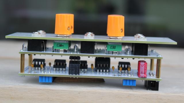
Figure 5: Side View
there is no calibration needed. but the potentiomenter knobs have to be aliged to center position.
the input jacks are wired to 5 volts when nothing is connected.
all channels are mixed to the out jack. when something is connected to the channel out, this channel is removed from the overall mix.
mixer
attenuverter