Danger
This is a preview of the elektrophon website, the content may not be accurate and is subject to change without any notice.
Summe is a simple mixer utility module. It can be used as a mixer, attenuator or attenuverter for AC and DC signals.
The function depends on the patching and settings of the potentiometers. When the potentiometer is at the centre position, the output signal is muted. No output signal is present. When turning to the right, the output will get louder until the output signal is equal to the input. When turning the potentiometer to the left, the output signal will be phase-shifted by 180°.
The first input is wired to a default DC voltage of +5V. With this input is not connected this voltage will be added as an offset to the mixed signal. With the potentiometer, the offset can be adjusted from -5V to +5V.
The output jacks are switched. When something is plugged into an output, this output is removed from the summed output. This channel is a simple attenuverter.
Figure 1: Summe Block Diagram
One interesting thing about the circuit is the attenuverter section. It uses an OPAMP in a differential configuration[1]. The resistors $R_3$ and $R_4$ are replaced with a potentiometer to make them adjustable.
Figure 2: Attenuverter Schematic
Above is the formula of the OPAMP differential amplifier. There are also the Resistors $R_5$ and $R_6$. These resistors make the response of the potentiometer logarithmic [2]. To calculate that these Resistors are in parallel to the Resistors $R_3$ and $R_4$.
$$ \begin{array}{c} Vout = \Bigl(1 + \frac{R2}{R1}\Bigr) \Bigl(\frac{\Bigl(\frac{R4*R6}{R3+R5}\Bigr)}{\Bigl(\frac{R3*R5}{R3+R5}\Bigr)+\Bigl(\frac{R4*R6}{R3+R5}\Bigr)}\Bigr) * V2 - \Bigl(\frac{R2}{R1}\Bigr) * V1 \end{array} $$Figure 3: Attenuverter Potentiometer Sweep
The calculation shows the Result with a 5V input and a potentiometer sweep from 0-100%. The last curve shows the logarithmic result simulated with spice. It overlaps the calculated line.
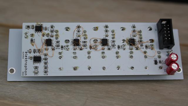
It may be that the summing amplifier is not stable and self oscillates. In this case, small capacitors can be added to stabilize the signal.
| # | reference | value | description | |
| 2 | C1 C2 | 22u | Aluminium Electrolytic Capacitor, 35V, D=5 mm, LS=2 mm | |
| 12 | C3 C4 C5 C6 C7 C8 C11 C12 C13 C14 C15 C16 | 0.1u | Multilayer Ceramic Capacitors MLCC | |
| 2 | C9 C10 | 100p | Multilayer Ceramic Capacitors MLCC | |
| 4 | D1 D2 D3 D4 | LED (Green/Yellow) | LED 3mm bipolar | |
| 1 | D5 | LED (Red/Yellow) | LED 3mm bipolar | |
| 1 | J1 | IDC Header | Pin Header IDC, 10 Pos, 2.54mm | |
| 4 | J2 J3 J4 J5 | IN | 3.5mm Eurorack Jacks | |
| 5 | J6 J7 J8 J9 J10 | OUT | 3.5mm Eurorack Jacks | |
| 2 | R1 R2 | 10 | Metal Film Resistors - Through Hole (L=3.6 mm, D=1.6 mm, 1%) | |
| 8 | R3 R4 R5 R6 R7 R8 R9 R10 | 47k | Thick Film Resistors - SMD (0805) | |
| 15 | R11 R12 R13 R14 R15 R16 R17 R18 R24 R25 R26 R27 R31 R33 R36 | 100k | Thick Film Resistors - SMD (0805) | |
| 5 | R19 R20 R21 R22 R39 | 1k | Thick Film Resistors - SMD (0805) | |
| 1 | R23 | 8.2k | Thick Film Resistors - SMD (0805) | |
| 5 | R28 R29 R30 R32 R34 | 500 | Thick Film Resistors - SMD (0805) | |
| 4 | RV1 RV2 RV3 RV4 | 100k | Alpha 9 mm Pots – Vertical | |
| 1 | U1 | LM4040BIM3-5.0 | Precision Micropower Shunt Voltage Reference | |
| 6 | U2 U3 U4 U5 U6 U7 | TL072 | Low-Noise FET-Input Operational Amplifiers (SOIC-8 ) |

Figure 5: Opamp Failure
The first input jack is wired to 5 volts when nothing is connected.
All channels are mixed to the out jack. when something is connected to the channel out, this channel is removed from the overall mix.
mixer
attenuverter